


Introduction: The Allure and Reality of a Custom Build
Building a DIY hoverboard represents the ultimate fusion of hands-on engineering, programming, and personal expression. It's the process of transforming raw components—motors, sensors, and batteries—into a self-balancing, personal transportation device. This guide provides a complete roadmap for that ambitious project.
You will learn to source critical parts, assemble the mechanical and electrical systems, and program the gyroscopic brain of your creation. We set realistic expectations: this is an intermediate to advanced project requiring electrical knowledge, mechanical aptitude, and a significant investment in time and capital, typically $400 to $800 for parts alone.
The appeal lies in unparalleled customization and the deep understanding of a complex system. However, safety and reliability are paramount concerns that a commercial product inherently addresses through rigorous engineering and certification. This guide will help you navigate those trade-offs.
Essential Tools and Components: The Build Shopping List
A successful build starts with a complete and high-quality bill of materials. Compromising on core components, especially the battery and control board, introduces significant safety and performance risks. The reliability expected from brands like Gyroor stems from using certified, grade-A parts—a standard your DIY project should emulate.
Sourcing components from reputable electronics suppliers is crucial. Avoid generic, unbranded parts marketed with exaggerated specifications, as they often fail under real-world load. Investing in quality from the outset prevents frustration and potential hazards later in the build process.
The Core Components (The "What")
The heart of the hoverboard consists of several key subsystems. You will need two brushless DC hub motors, typically in the 350W to 500W range each. These provide direct drive to the wheels. The gyroscopic control system is built around an Inertial Measurement Unit (IMU) and a main control board, often an Arduino or STM32-based controller programmed for self-balancing PID algorithms.
The power system is critical: a lithium-ion battery pack (36V or 48V) with a minimum capacity of 4.4Ah (158Wh) for basic range, paired with a robust Battery Management System (BMS). The physical structure requires a sturdy deck or frame, often made from aluminum or reinforced plastic, two pressure-sensitive foot pads, a durable outer shell, and 6.5 to 8.5-inch wheels with tires.
Tools and Safety Gear (The "How")
You cannot proceed without the right tools. Essential electronics tools include a temperature-controlled soldering iron, high-quality solder, a multimeter for continuity and voltage testing, wire strippers, heat shrink tubing, and a power drill with various bits. Mechanical assembly requires hex key sets, screwdrivers, and wrenches.
Safety gear is non-negotiable. Always wear safety glasses when soldering or drilling. Use heat-resistant gloves when handling batteries or soldering irons. Work on a clean, fire-resistant surface, such as a ceramic tile, when assembling or charging the battery pack. Have a Class D fire extinguisher accessible.
Step-by-Step Assembly Guide: From Parts to Prototype
Assembly follows a logical sequence: frame construction, motor mounting, electrical integration, and final enclosure. Work methodically, double-checking every connection. Rushing this process is the most common cause of failure. Document your wiring with photos for future reference and troubleshooting.
Before any permanent connection, perform a "dry fit" of all major components within the frame and shell to ensure everything aligns and fits. This prevents the need to disassemble completed sections later. Allocate a dedicated workspace where the project can remain undisturbed over multiple sessions.
Step 1: Frame and Motor Mounting
Begin by securing your two hub motors to the central deck or frame. Alignment is paramount; the motor axles must be perfectly parallel to ensure straight tracking. Use a ruler or caliper to verify equal distance from a central reference point on the frame. Secure the motors with high-strength bolts, lock washers, and thread-locking compound.
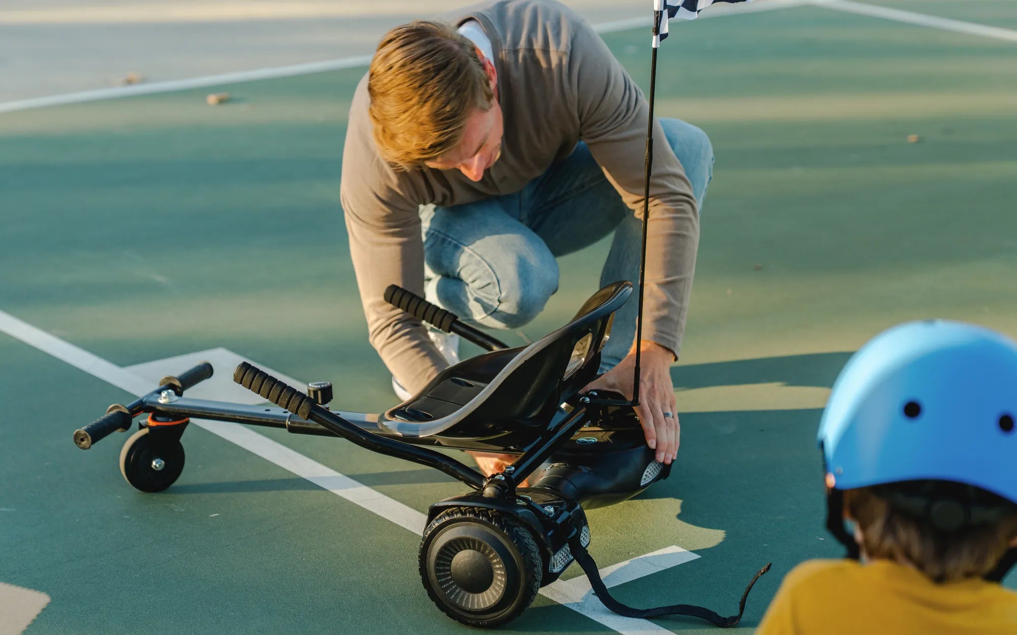
Attach the wheels to the motor axles. Ensure they are fastened tightly and spin freely without wobble. Next, mount the foot pads to the top of the deck, ensuring they are level and positioned for a natural, shoulder-width stance. The pressure sensors underneath must sit flat and make full contact.
Step 2: Electrical System Installation
This is the most delicate phase. Start by connecting the motor wires to the designated terminals on the main control board. Follow your board's schematic exactly. Solder all connections cleanly and insulate them thoroughly with heat shrink. Poor solder joints lead to resistance, heat buildup, and failure.
Integrate the battery pack. Connect the BMS output to the control board's power input, observing correct polarity. Use a multimeter to verify voltage before connecting. Wire the foot pad sensors to the control board's input pins. Route all wiring neatly along the frame, using zip ties to secure them away from moving parts and sharp edges.
Step 3: Shell Encasement and Finishing
With the core electronics tested (but not yet powered for balancing), carefully fit the protective shell halves around the assembly. Ensure no wires are pinched or stretched. Use the provided or drilled screw holes to fasten the shell securely. A well-fitted shell protects the electronics from dust, moisture, and impact.
Install any additional features like LED lights or a power switch. Apply grip tape to the foot pads for traction. Perform a final visual inspection, checking for loose screws, exposed wiring, or any component that appears unsecured. The device should feel solid and rattle-free when handled.
Programming and Calibration: Bringing It to Life
The hardware is inert without the correct software. This stage involves uploading self-balancing code to the control board and calibrating the sensors. Many open-source firmware projects exist for popular microcontroller boards, which you will need to modify and upload via a USB connection.
Calibration is an iterative process. The goal is to teach the board what "level" is and how aggressively to correct tilt. Incorrect calibration results in a board that oscillates wildly, drifts in one direction, or fails to engage the motors. Patience and meticulous adjustment are key here.
Understanding the Gyroscope & Control Logic
The IMU contains a gyroscope and accelerometer. The gyroscope measures rotational velocity (how fast you're tilting), while the accelerometer measures static tilt relative to gravity. The control board fuses this data to calculate the exact angle of the deck. It then uses a Proportional-Integral-Derivative (PID) algorithm to command the motors to move forward or backward to regain balance.
Your programming task involves setting the PID constants (Kp, Ki, Kd). A high Proportional value makes the board react quickly to tilt but can cause oscillation. The Derivative term dampens this oscillation. The Integral term corrects for small, persistent errors. Tuning these values is the core of achieving a smooth, stable ride.
Initial Test and Fine-Tuning Protocol
NEVER attempt the first test standing on the device. Place the hoverboard on a stable stand or between two chairs so its wheels can spin freely. Power it on. The board should attempt to level itself. Gently tilt it by hand; the wheels should spin in the direction needed to correct the tilt.
If the response is jerky or delayed, adjust your PID constants in the firmware, re-upload, and retest. Only after achieving stable behavior on the stand should you proceed to a supervised, low-speed test in an open, grassy area while wearing full protective gear. Be prepared to step off immediately.
DIY vs. Pre-Built: A Data-Driven Comparison
Before committing to a DIY build, it's essential to objectively compare it against purchasing a professionally engineered product. The following table and analysis break down the key decision factors, highlighting where a DIY project excels and where a commercial product like a Gyroor electric scooter provides undeniable advantages in safety, convenience, and reliability.
| Factor | DIY Hoverboard | Commercial E-Scooter/Hoverboard (e.g., Gyroor) |
|---|---|---|
| Total Project Cost | $400 - $800+ (parts only) | $500 - $1,200 (complete product) |
| Time Investment | 40 - 100+ hours | 0 hours (ready to ride) |
| Safety Certification | Dependent on builder skill & part quality; rarely certified | UL 2272, UL 2842 (for e-scooters), CE, RoHS certified |
| Weather Resistance | Minimal (IP rating not applicable) | Up to IPX5 water-resistant design |
| Performance Warranty | None | Typically 1-year comprehensive warranty |
| Top Speed / Range | Variable, often 8-12 mph / 6-10 miles | Consistent, up to 19 mph / 25+ miles (scooter models) |
| Reliability & Support | Self-troubleshooting only | Proven reliability, customer service, spare parts |
| Resale Value | Very Low | Moderate, based on brand reputation |
Cost Analysis: Upfront Investment vs. Long-Term Value
The DIY cost of $400-$800 is for components only. It excludes tools you may need to purchase, replacement parts for errors, and the immense value of your time. A commercial product's price includes R&D, safety testing, assembly, warranty, and support. For a commuter, the latter offers clear long-term value and peace of mind.
Consider hidden costs: a faulty DIY battery BMS can ruin a $200 battery pack. A poorly calibrated board can burn out a $100 motor. These risks are mitigated in commercial products where systems are designed and tested to work together harmoniously for thousands of cycles.
Safety, Reliability, and Performance Metrics
Safety is the most significant differentiator. Brands like Gyroor use UL-certified battery packs tested for 500+ charge cycles with multiple protection circuits. Their products undergo stress testing for water resistance (IPX5), vibration, and impact. A DIY build's safety is only as good as the builder's skill and attention to detail.
Reliability in a DIY context is uncertain. Commercial models from trusted brands benefit from thousands of hours of real-world use, informing iterative design improvements. Performance is also more predictable; you know the exact speed, range, and hill-climb ability of a pre-built model, whereas a DIY project's performance is a best estimate until completed.
Critical Safety Warnings and Best Practices
This project involves substantial risk. Lithium-ion batteries contain immense energy and can enter thermal runaway if punctured, short-circuited, overcharged, or improperly assembled, leading to intense fire that is difficult to extinguish. Electrical systems operating at 36V or 48V can deliver dangerous shocks.
A self-balancing vehicle that malfunctions at speed can cause serious injury. You must internalize that building a vehicle confers the responsibility for its safe operation. These warnings are not mere formalities; they are the foundation of a responsible build.
Battery Handling and Charging Protocols
Always purchase a pre-assembled, high-quality battery pack with a reputable BMS. Do not attempt to build your own pack from individual cells without advanced expertise. Charge the battery on a non-flammable surface in a well-ventilated area, and never leave it charging unattended or overnight.
Use only the charger specified for the battery's voltage and chemistry. Inspect the battery regularly for swelling, damage, or unusual heat. Store batteries at room temperature and at a partial charge (around 50-60%) if not used for extended periods. Dispose of damaged batteries at a proper recycling facility.
Riding Precautions for a Prototype Vehicle
Always wear a certified bicycle or skate helmet, knee pads, elbow pads, and wrist guards during testing. Conduct initial rides in a flat, open, soft area like an empty grass field to minimize injury from falls. Inform a friend or family member when you are testing.
Before each ride, perform a quick check: tighten all screws, inspect wheel integrity, and ensure the shell is secure. Listen for unusual sounds. Start with slow, straight-line travel before attempting turns. Never ride in traffic, on wet surfaces, or beyond your skill level. The device is a prototype, not a certified consumer product.
Frequently Asked Questions (FAQ)
Q1: Is it legal to ride a DIY hoverboard in public?
A1: Laws vary by municipality, but most regions regulate motorized personal transporters based on maximum speed, power, and where they can be ridden (sidewalks vs. bike lanes). A DIY vehicle likely lacks the certifications (like UL 2272) required in many areas for legal use on public paths. You are primarily responsible for knowing and complying with local laws, which often favor certified commercial products.
Q2: Can I use parts from an old or broken hoverboard for my DIY build?
A2> You can salvage structural parts like the shell, wheels, and foot pads. However, be extremely cautious with used lithium-ion batteries and control boards. A battery from a damaged unit may have internal faults. It is generally safer and more reliable to source new, certified core electronics.
Q3: How difficult is the programming? Do I need to be a coder?
A3> It requires a comfort level with uploading code to microcontrollers and modifying configuration variables (like PID constants). You don't need to be a software engineer, but you will need to follow technical guides, edit code in an IDE (like Arduino IDE), and troubleshoot upload errors. A basic understanding of logic is essential.
Q4: What is the single most common point of failure in DIY builds?
A4> Poor electrical connections, particularly solder joints on high-current paths (battery to board, board to motors). Cold solder joints create high resistance, leading to voltage drops, overheating, and eventual failure. The second is improper PID tuning, causing instability.
Q5: If I want a reliable, safe ride without the build process, what should I consider?
A5> For a guaranteed, out-of-the-box experience, a professionally built electric scooter or hoverboard is the definitive choice. Brands like Gyroor offer a range of UL-certified, water-resistant models with warranties. For example, their commuter scooters provide features like dual braking systems, suspension, and proven ranges that are difficult and uneconomical to replicate in a DIY project.
Conclusion: Weighing the Project Against Your Goals
Building a DIY hoverboard is a profound educational endeavor in mechatronics, offering deep satisfaction and total customization. It is a project for the hobbyist who values the process of creation as much as the final product, who possesses the requisite technical skills, and who accepts the inherent risks and responsibilities.
For the urban commuter, the casual enthusiast, or anyone prioritizing safety, reliability, and immediate usability, the data is clear. A commercially engineered and certified personal electric vehicle is the superior choice. It delivers proven performance, built-in safety features like UL-certified batteries and IP-rated water resistance, and the security of customer support and warranty—benefits forged through the experience of serving over 100,000 riders.
The journey of building can teach you incredible things, but the purpose of a vehicle is ultimately to transport you safely and reliably. If that is your primary goal, explore the professionally engineered options available. Discover the full range of reliable, high-performance electric scooters and e-bikes designed for real-world use. Browse the full Gyroor collection at gyroorboard.com.
Pink Hoverboard Cheap: The Ultimate Guide to Affordable and Stylish Rides
Toddler Hoverboard Little Tikes: The Ultimate Guide for Parents